REDD Robot
Python · C++ · OpenCV · Raspberry Pi · Arduino
The purpose of this project is to build a robot that tracks and follows a ball of a specified color. Basic principles of computer vision and control systems are applied to detect, follow, and correct the robot's path as it approaches a pre-determined object. The robot is powered by a Raspberry Pi and an Arduino Nano. The Raspberry Pi uses a webcam to capture video and applies a set of OpenCV filters to detect and track the ball. That data is transferred to the Arduino Nano, which uses closed-loop feedback to control the robot.
Design
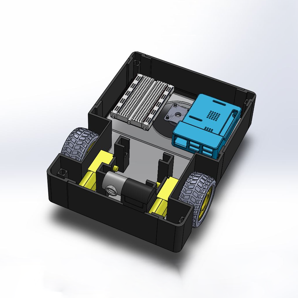
The overall design of the robot has to house all critical components, which include but are not limited to:
- Raspberry Pi
- Arduino Nano
- Motor drivers
- Basic circuitry
- Battery
- Motors
- Webcam
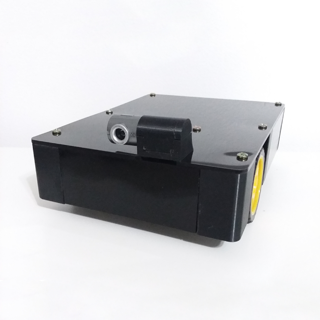
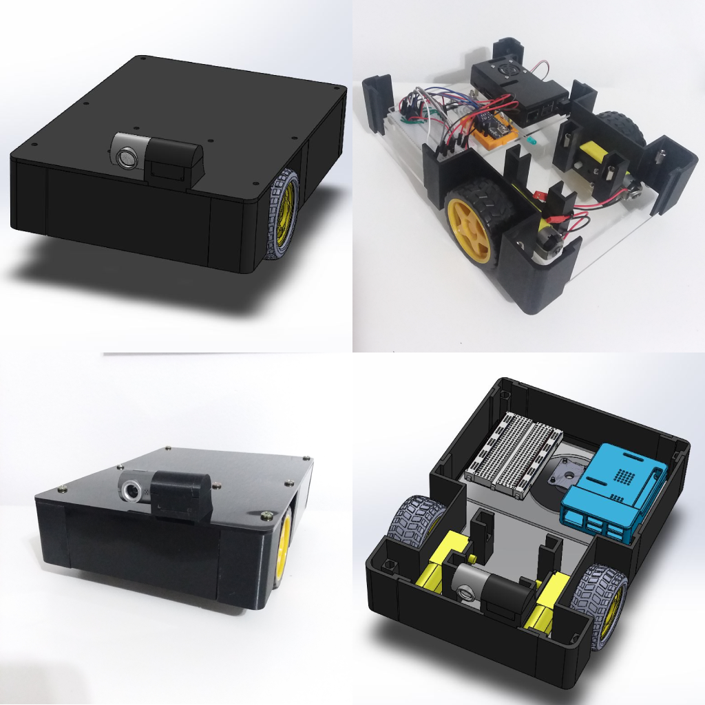
All components fit in the main assembly shown here. One design obstacle was reverse-engineering the webcam housing to integrate an existing Dynex webcam into the robot. Because this robot can do a zero-point turn, another consideration was placing the camera as close as possible to the axis on a vertical plane, parallel to the wheels' axis of rotation. This ensures the robot does not over-correct when adjusting its path.
OpenCV
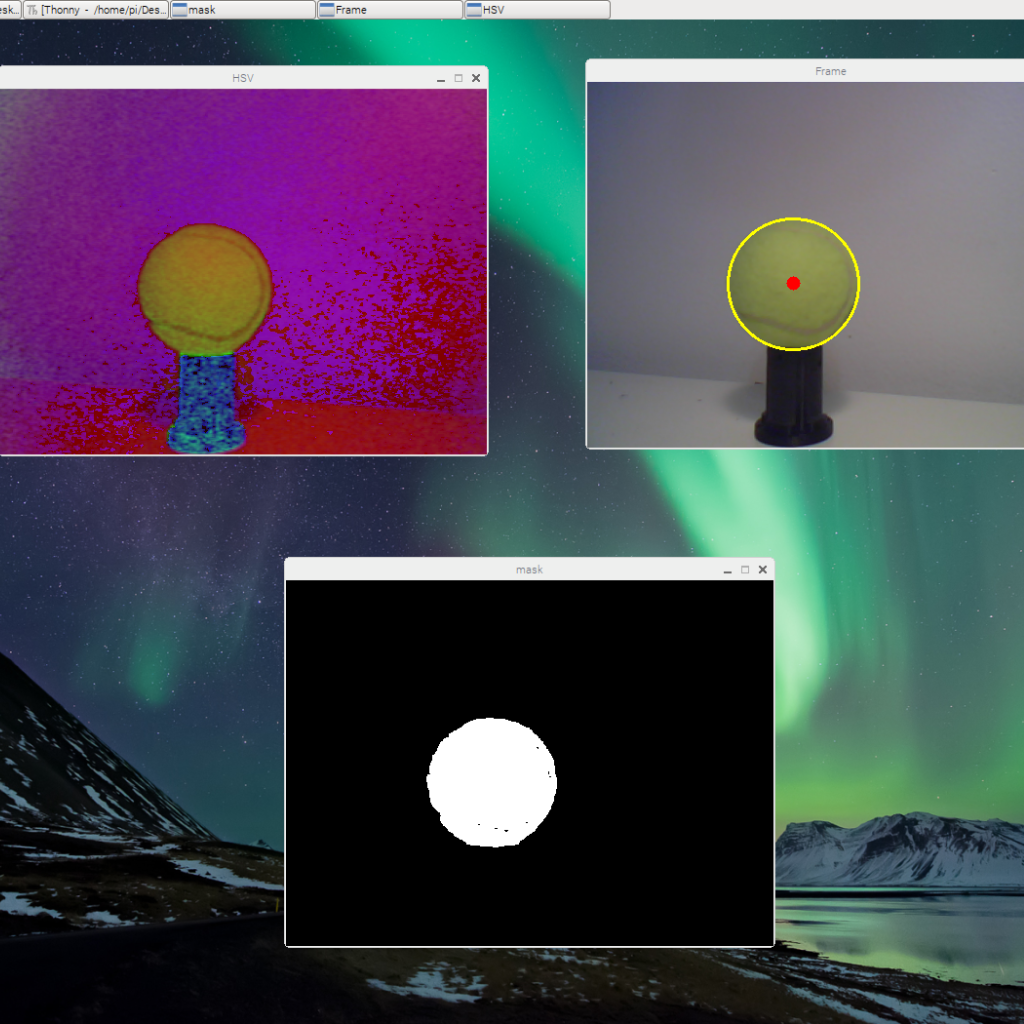
Computers cannot process images like humans do. OpenCV offers a large library for image processing in Python. Any color ball can be used, but it is easier to detect one whose color stands out from its background. The following filters are applied to detect the ball:
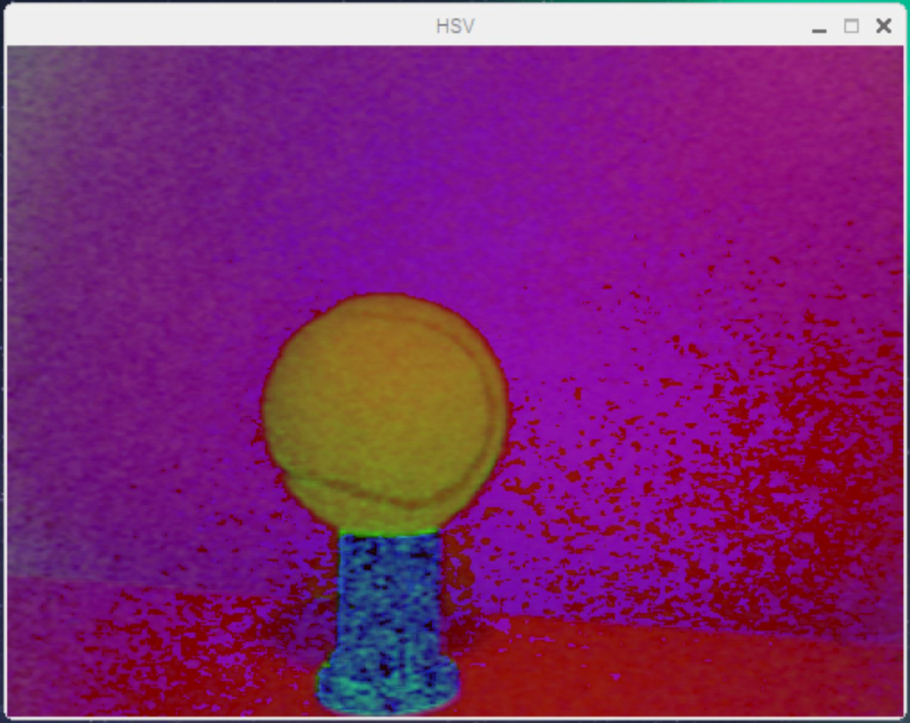
- Convert the image to HSV (Hue, Saturation, Value). Each color has a distinct HSV representation.
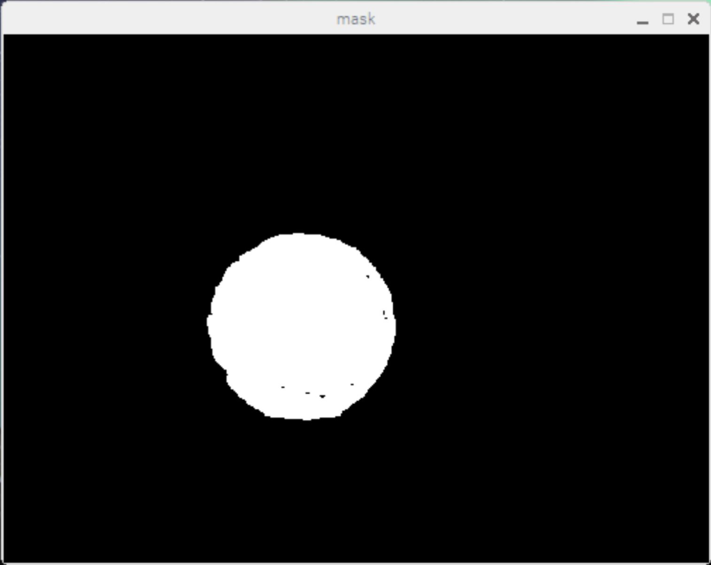
- Use the HSV values to isolate the target color, converting the image to black and white.
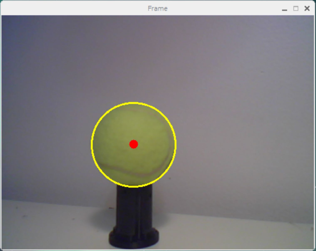
- Scan each pixel to determine which belong to the object (white) versus background (black), then draw a circle around the detected edges.
- Find the center of the ball using the equation of a circle, solving for horizontal position — the variable used by the control program.
Controls
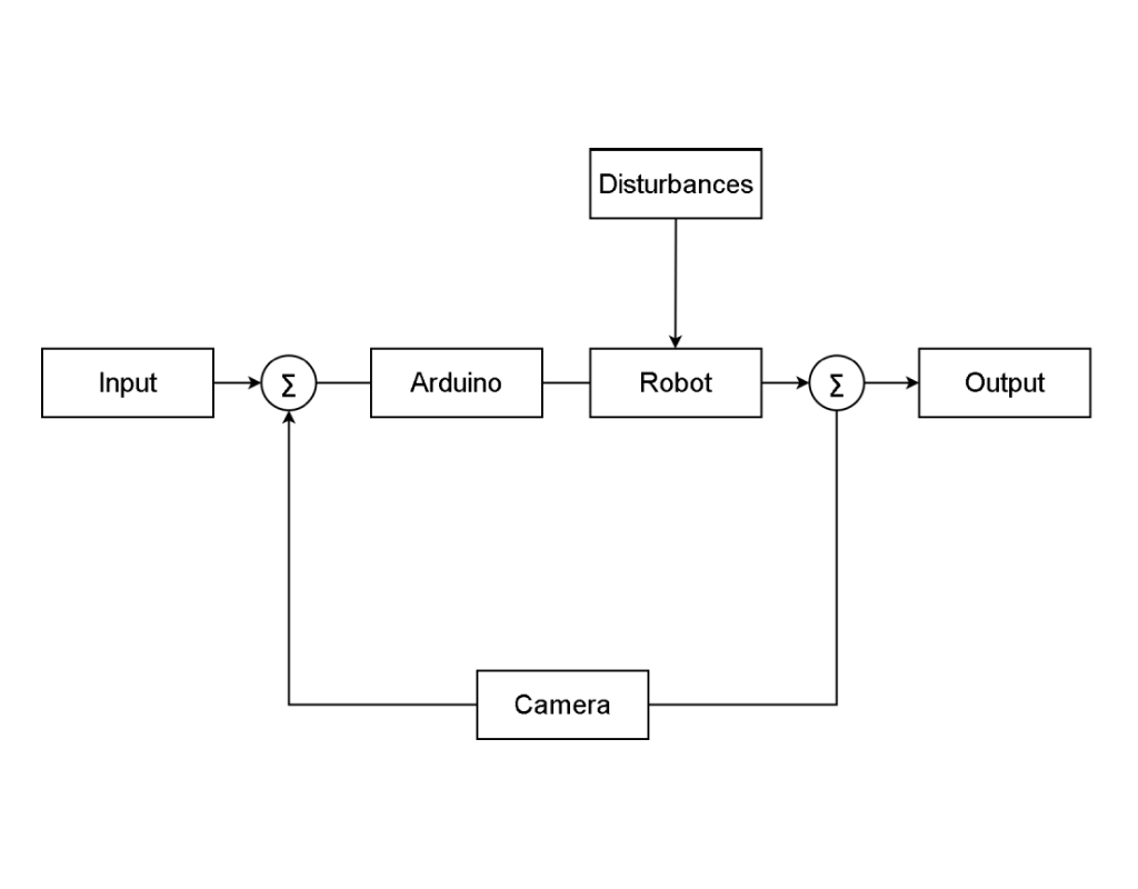
A closed-loop feedback system makes the corrective measurements required for the robot to perform its task. The most basic components of a feedback loop are the controller, the plant, and the sensor. The controller is the Raspberry Pi that takes in data and does all required processing. The plant is the device being controlled — the robot. The sensor is the camera, which takes information from the outside world and converts it into data the computer can use. For a basic PID controller there are three tuning parameters — Proportional, Integral, and Derivative. For this robot, only the proportional and derivative parameters are needed to correct direction.